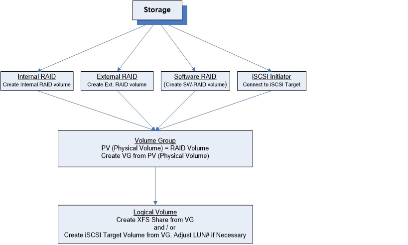
3. Menu - Storage
3.1 Build-in RAID model, Hardware RAID Model, and Gateway model
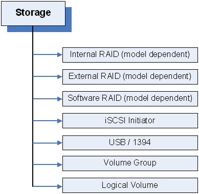
Sans Digital’s NAS has 3 models: Hardware RAID, Gateway, and Built-in RAID.
Built-in RAID – The NAS has no internal hardware RAID controller, the OS based built-in RAID is used for RAID creation, rebuild and calculation. When a NAS is Built-in RAID model, the “Software RAID” sub-menu will be the main page for RAID management.
The “Software RAID” sub-menu can also be use when NAS are equipped with multiple RAID controllers or subsystems to create a single volume. In this case, only RAID 0 should use in this configuration, since RAID controller card or subsystems will create and manage higher RAID level, such as RAID 5, or RAID 6.
Build-in RAID model includes the following models:
- AccuRAID Series: AN4L+, AN4L+B, AN4L+BBKU, AN4L+BLT5 AN5L+B, AN6L+B, AN8L+B, AN12L+B
- MobileNAS Series, MN4L
- EliteNAS Series: EN208L, EN212L, EN208L12S, EN212L12S
Hardware RAID –The NAS has an internal PCIe based Hardware RAID controller. Data are storage within the same enclosure, connected to the internal RAID controller. Hardware RAID model provide RAID engine offload to generate higher performance. The “Internal RAID” a sub-menu entry will display. Otherwise, this sub-menu entry will not display.
Hardware RAID model includes the following models:
- EliteNAS Series: EN208L+BXE, EN212L+BXE, EN316L+BXE, EN424L+BXE, EN850L+BXE, EN872L+BXE
- EliteNAS 12G Series: EN208L12, EN212L12, EN316L12, EN424L12, EN436L12, EB850L12, EN872L12
Gateway –The NAS has no internal storage at all; rather it is only a head unit that connects to external RAID subsystems via Fibre Channel or SAS connectivity for storage capacity. The “clustering” solution requires the Gateway model to implement. When the NAS is purchased as “Gateway” model, the “External RAID” sub-menu entry will display, otherwise, it is hidden from the sub-menu.
Gateway model are typically order directly from Sans Digital.
3.2 Internal RAID
Multiple RAID Controller Support
When there is only one internal RAID controller installed, it will display as:
Launch RAID Manager for Controller #0
When there are multiple internal RAID controllers installed, it will display as:
Launch RAID Manager for Controller #0
Launch RAID Manager for Controller #1
Launch RAID Manager for Controller #2
…… …… …… …… …… …… ……
Click on the selected “……Controller #x” to launch the Web Admin GUI for the corresponding RAID controller.
The default login Info for the RAID Controller:
User ID: admin
Password: 0000
Note : If you have changed the password of the NAS, the new password of the NAS will sync to the RAID controller as well. Be cautioned that the Controller’s user ID remains as “admin” while the ID for the NAS remains as “root” .
Please refer to Hardware RAID controller User Manual for details on how to setup/configure the RAID array, and make sure you initialize the RAID volume(s).
Once the RAID controller has finished volume initialization, click “Restart” for the NAS to recognize the newly created RAID volume as the “Physical Volume”.
3.3 External RAID
The “External RAID” page will display only on the “Gateway/Head” model, otherwise this function hidden.
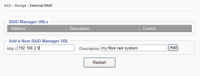
This function is designed for the external RAID GUI management that uses Web based GUI with IP address. If your external RAID GUI management is some sort of executable application program other than Web browser, then it is not covered by this function.
Fill the URL field with IP address of the External RAID’s GUI
Fill the Description field with a description for the URL.
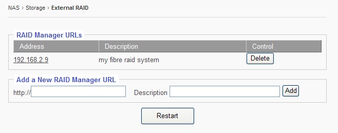
Then, click “Add. ”
Now click on the “IP” of the “RAID Manager URLs.” Doing so will bring up the Web GUI Management of your External RAID system.
3.4 Software RAID
The “Software RAID” page will display only for the “Built-in RAID” model, otherwise, this feature is hidden.
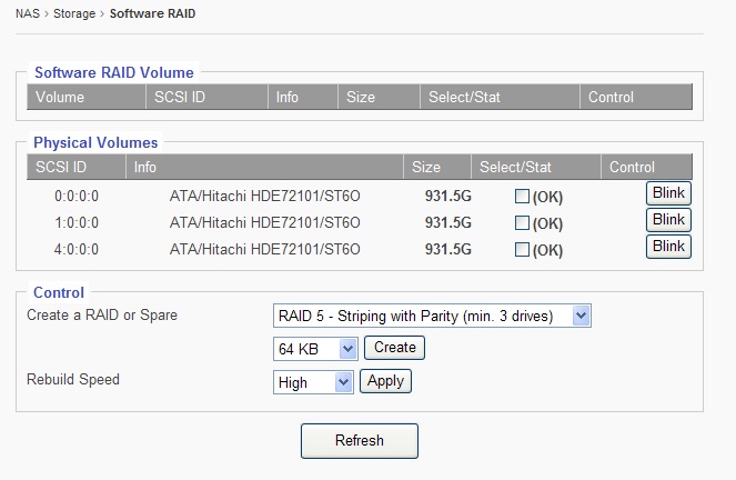
Under the “Physical Volumes”Window:
SCSI ID: Disk ID, in format of: 0:0:0:0 = disk-1
1:0:0:0 = disk-2
2:0:0:0 = disk-3
3:0:0:0 = disk-4
Info: disk Info, such as: Brand, Model, and Firmware
Size: Disk size
Select/Stat: Disk-selection/disk-status. The empty box means the disk is not selected. Check-marking the box selects his disc. Next to the box is that stat of the disc. “OK” means the disk is at normal status. It could show “Failed” or “Removed” if the disk is bad or removed.
Blink button: This feature blinks the LED on the Physical hard drive tray to help identify which hard drive is being referenced.
Create a RAID or Spare: When there are no existing RAID volumes, you can only create a RAID and will not be allowed to create a Spare. The Spare is allowed only if you have an existing RAID with RAID-level of: 1, 5, 6, or 10
Supported RAID-level is: 0, 1, 5, 6, or 10
Stripe Size: The stripe size for the RAID can be anywhere from 4KB ~ 1024KB. Option is selected via the drop down menu. The default size is 64KB
Rebuild Speed: The options are: High, Mid, and Low. This is used to define how much internal storage speed should be allocated to the RAID rebuilding, therefore, reserve a portion of resources for normal data accessing. The higher the rebuild speed is, the less resources it has for normal data access.
For first time RAID creations, always set rebuild speed to “High,” to decrease time needed to initialize RAID.
3.5 Basic Steps to Create a RAID
Step-1: select by check-marking all the disks to be put into the same RAID array.
Step-2: select the RAID-level
Step-3: select the Stripe-Size, or leave it at 64KB
Step-4: click the “Create” button, and the GUI will display the page below:
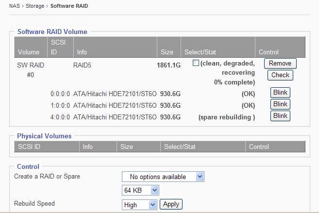
Notice that the disks selected have disappeared from the “Physical Volumes” window, and have shown up in the “Software RAID Volume” Window.

Now under the Software RAID Volume window, we have:
Volume: SW-RAID#0, if there are more than one SW-RAID, they will be, SW-RAID#1, SW-RAID#2, so forth and so on.
Info: RAID-Level Info, such as RAID5, or RAID0, or RAID6, etc.
Select/Stat: RAID volume-selection/RAID volume-status. When the selection box is empty, its means that the RAID is not selected.
Status can be: Normal, Degraded, Failed, Degraded recovering %, etc.
Remove button: Select by check-marking a RAID, and then if the “Remove” button is clicked, the selected RAID volume will be removed/deleted.
Check button: Select by check-marking a RAID, and then if the “Check” button is clicked, the selected RAID volume will run consistency check for RAID-level: 5 or 6.
Create a HotSpare: If the existing RAID-level is 5, 6, or 10, a HotSpare disk can be added to it.
Step-1: Select by check-marking a RAID volume from the Software RAID Volume window.
Step-2: Select a disk from the Physical Volume window.
Step-3: Click “Create.”
3.6 iSCSI Initiator
Sans Digital’s NAS has a built-in iSCSI initiator function which allows the administrator to pull in a remote iSCSI Target volume as the local physical volume.
Basic Steps to connect to a remote iSCSI Target / LUN:
Step-1: Check-marking “Enable Service” option box
Step-2: Key in the remote iSCSI Target’s IP address in “iSCSI Target Discovery - IP:”
Step-3: Key in the remote iSCSI Target port number if it is not the default 3260.
Step-4: Click the “Discover” button. If the Target IP is correct, the Target name will show up in the “Target List” window and the corresponding iSCSI LUN will show up in the “iSCSI LUN Log In and Out” window.
Step-5: Select the iSCSI LUN and click “Log In.”
For CHAP, please refer to the remote iSCSI Target’s requirement.
3.7 USB/1394 page
When an USB or 1394 disk is plugged into the system, a device and corresponding capacity will be displayed in the “Raw USB/1394 Volume Pool” window.
Give it a name in the “Name” field and click “Import” and the format screen will appear.
Once it is formatted, it will show up in the “USB/1394 Volume Pool” and be ready to be used.
USB/1394 disk is intended to be removable, and removing a XFS volume while online can disrupt the entire OS and all volumes. Therefore, the USB/1394 volume is defaulted to be “FAT32,” which in turn limits the volume size to a 2TB maximum.
USB/1394 volume is a logical volume, therefore there is no need to go through the settings in the “Volume Group” page and “Logical Volume” page.
Depending on the chip used in the motherboard/system and the chip used in the external Device, sometimes they are not compatible, so in such a case the USB/1394 disk will not be supported.
3.8 Volume Group page
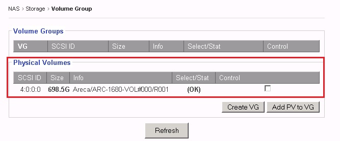
After the Internal RAID volume/External RAID volume/iSCSI Target volume has been created and the NAS restarted, the volume will show up in the “Physical Volumes” window.
Check-mark to select the Physical Volume (aka PV), and click the “Create VG” button.
Now, the selected PV will turn into VG and display under the “Volume Group” window.
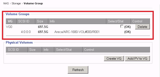
With multiple PVs, multiple VGs can be created.
To increase the size of an existing VG, just simply add a new PV to the existing VG by check-marking both the PV and VG, and then clicking “Add PV to VG”.
Adding a PV to an existing VG is also called: Linear RAID or Spanning.
a s
3.9 Logical Volume page
This is the last step in creating the network volume or iSCSI Target volume.
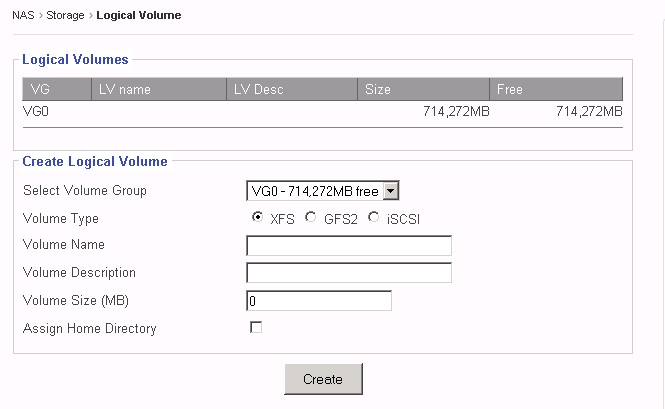
Volume Types:
XFS – a XFS volume is to be created for network share(s).
“Assign Home Directory” is an option used to create a “home” folder for each user on that network share. Regardless of how many XFS shares you may have, only one XFS share can be used to create “home” folder.
GFS2 – a GFS2 volume is to be created for clustered network share(s), and only shows when a special license is entered. Otherwise, it is hidden. The special GFS2 license is only available for the Gateway/Head Model.
iSCSI – an iSCSI volume is used to create the iSCSI target volume, and it will act as a local disk to the remote iSCSI initiator.
iSCSI target volume has an extra field: LUN#
By default, the LUN# = 0. However, if you are using multiple iSCSI target volumes from multiple NAS units with VMWare ESX, then you might need to adjust the LUN# on them so that no two iSCSI target volumes will have the same LUN# . Otherwise, ESX will assign the exact same ID to all the volumes and won’t connect properly.
This is a typical illustration for how it looks like after a typical XFS share and an iSCSI target volume are created.
VG0 – It has 714,272MB in size, it has two LVs created on it, and it has 414,272MB free space for more LVs.
share0 – It is a XFS share from VG0, it has size of 200,000MB, which is all free.
ivolume – It is an iSCSI target volume from VG0, it has size of 100,000MB, and since contents of an iSCSI volume is solely controlled by the iSCSI initiator, and the NAS will not show the Free space of it.
XFS volume and/or iSCSI target volume can be deleted by clicking “Delete.”
But they can also be “Modified.” See next page for details.
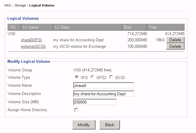 When clicking on an existing LV name, the “Modify Logical Volume” window will display the corresponding LV info.
In the “Modify Logical Volume” window, you can do:
* Change the volume name – Enter the new volume name replacing
the old volume name.
* Increase the volume size – If the VG still has free/available space, then enter the new larger size for the Volume Size.
Click “Modify” to save and apply changes or click “Back”to cancel.
In next page, we will review the process and workflow of creating LV.
